
Building the Rover transverter for the 1296 MHz I experience the lower power output than expected, so I start looking what can cause this 10 dB lower output than predicted. Not only on the TX side, I notice the lower signal also on the RX side comparing the received signal with the other transverter design with the similar conversion gain. Among the all other parts affecting the signal loss, the filter is the only one that was designed and not fabricated. Paul, the author already made a good job with all relevant measurements on the filter, already published, but I wanted some other verifications to get some more data to be able to use the same filter in some other projects.

The filter was duplicated from the W1GHZ 1296 MHz transverter (3 pole) on the standard 1.6mm FR-4 laminate. I prefer to use the "toner transfer" technique with my flat iron. Iron already became the standard tool on my workbench :-) A pair of SMA connectors are added to be able to measure and compare the filter more easily. Of course using the SMA connectors bring some additional losses to overall measurements, but I can live with that. The filter itself in the transverter configuration will have even lower I.L.
IMPORTANT !!! The following measurements are done with the reference signal of -12.72 dBm !!!
So the reference signal was not 0 dBm, but -12.72 dBm and it is necessary to correct all the readings that you see on the following spectrum analyser screen shots. I start with the center frequency (C.F.) 1296 MHz, span 500 MHz to see quickly if my flat iron was successful or not :-) Quick look on the curve and everything looks as predicted. The filter is centered around the 1296 Mhz with the I.L of -4.53 dB (17.25dBm -12.72dBm). Looking the screen the BW - 3dB is 100 MHz.

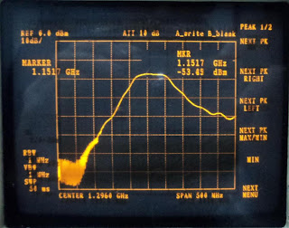
The next step was to measure the filter response 144 MHz from the center frequency. At 1152 Mhz the signal was 40.28 dB down as per screen shot. I forget to measure the signal on 1440 MHz but we can see that the skirt is not so good as on the lower side, so the signal is only 23.28 dB down on the 1440 MHz. Of course "Right side up" mixing approach should work better than using the higher L.O. frequency in this case.
As I plan to use the same transverter but with the I.F. 432 MHz I measure the filter response on the 864 MHz with signal 62.28 dB down. The center frequency is 1296 MHz and the span is 900 MHz, 10dB/div. Despite the mixing products problem using the 432 MHz for the I.F. transverter is working quite good with this filter.

Using the same filter with the I.F. of 50 MHz to work on 1296 MHz is almost impossible. The signal on 1246 MHz is down only 11.28 dB. This measurement was just to compare this filter skirt with some other filters measured before. So here is the screenshot.

When measured the filter bandpass and the loss, I was still curious about the filter return loss / SWR so additional test was performed using the network analyser. This measurement gave me quite good idea about the characteristics where the minimum obtained R.L. was 16.29 dB or the SWR of 1:1.36. This way I was quite sure that the mixer RF port is terminated with the impedance close to 50 ohms.


The next step was to measure the filter response 144 MHz from the center frequency. At 1152 Mhz the signal was 40.28 dB down as per screen shot. I forget to measure the signal on 1440 MHz but we can see that the skirt is not so good as on the lower side, so the signal is only 23.28 dB down on the 1440 MHz. Of course "Right side up" mixing approach should work better than using the higher L.O. frequency in this case.

As I plan to use the same transverter but with the I.F. 432 MHz I measure the filter response on the 864 MHz with signal 62.28 dB down. The center frequency is 1296 MHz and the span is 900 MHz, 10dB/div. Despite the mixing products problem using the 432 MHz for the I.F. transverter is working quite good with this filter.

Using the same filter with the I.F. of 50 MHz to work on 1296 MHz is almost impossible. The signal on 1246 MHz is down only 11.28 dB. This measurement was just to compare this filter skirt with some other filters measured before. So here is the screenshot.

When measured the filter bandpass and the loss, I was still curious about the filter return loss / SWR so additional test was performed using the network analyser. This measurement gave me quite good idea about the characteristics where the minimum obtained R.L. was 16.29 dB or the SWR of 1:1.36. This way I was quite sure that the mixer RF port is terminated with the impedance close to 50 ohms.


At the end, I tried to tune the filter for even better RL, what was possible but on the other side affecting the pass-band characteristic. This filter is designed as a no tune project and I was happy with the above presented results. They correlate much with all already published by Paul, W1GHZ. The small differences are result of maybe different FR-4 used, slightly different dielectric constant, or the fact that my filter was not covered - galvanised. Non uniform Er can also affect the results where FR-4 has quite loss on microwave frequencies. Of course, the "Right side up" version of the transverter is using the 4-section hair pin filter with little bit different characteristics, but why not believing to Paul who already made all relevant measurements.
To summarise:
Freq: 1296 1152 1440 1246 864 MHz
Loss: 4.53 40.28 23.28 11.28 62.28 dB
supericka ,jako lijepo ,cestitam ...3XZ
ReplyDeleteSuper --- thanks
ReplyDeletegood filter. Can this design be made using the CSt studio suite 2018?
ReplyDeleteHello, Do you need an emergency loan to address your financial needs? We offer loans ranging from 3,000.00 to 100,000,000.00 EUR, we are reliable, powerful, fast and dynamic, without credit control and we offer a 100% guarantee for foreign loans during the transfer period. We have also issued a loan in all currencies with a 2% interest rate for all loans .... If you are interested, contact us through Via (Whats App) number:+919394133968 patialalegitimate515@gmail.com Mr Jeffery
ReplyDelete
ReplyDeleteGET OUT OF FINANCIAL MESS WITH THE HELP OF drbenjaminfinance@gmail.com
I have been in financial mess for the past months, I’m a single mum with kids to look after. My name is REBECCA MICHAELSON, and am from Ridley Park, Pennsylvania. A couple of weeks ago My friend visited me and along our discussion she told me about DR BENJAMIN OWEN FINANCE of (drbenjaminfinance@gmail.com); that he can help me out of my financial situation, I never believed cause I have spend so much money on different loan lenders who did nothing other than running away with my money. She advised, I gave it a try because she and some of her colleagues were rescued too by this Godsent lender with loans to revive their dying businesses and paying off bills. so I mailed him and explain all about my financial situation and therefore took me through the loan process which was very brief and easy.. After that my loan application worth $278,000.00USD was granted, all i did was to follow the processing and be cooperative and today I am a proud business owner sharing the testimony of God-sent Lender. You can as well reach him through the Company WhatsApp +19292227023 Email drbenjaminfinance@gmail.com