Tuesday, December 25, 2012

5.7 GHz poor guy transverter

Not so many simple transverters for 6cm band seen up to now. So here is one, really simple and working, with minimum parts required and poor guy like me did find all the parts within the pile of microwave "LEGO bricks".

The architecture is traditional and straightforward, no bells and whistles in this design. The core of the transverter is the mixer. Simple as it can be, SKY-60 double balanced mixer working up to 6GHz with affordable price, new through the e-bay purchase. Drive on the IF port 0dBm @ 432MHz, +7dBm @ 5328MHz for the LO port. On the output RF port we have LO, LO+432MHz and LO-432MHz signal present. To get rid of the unwanted signals the mixer is followed by the filter. Here we can use many types of filters but the pipe cap was a simple and cheap solution, can be tuned easily even with no special measuring equipment. Tune to peak method will give good results. Of course the frequency is 5760MHz. This filter will be used both , for RX and TX operation. PIN diodes, RF switch, relay, resistor splitter or Wilkinson divider. Well, the Wilkinson divider was appropriate and simple enough for this approach. More over, no switching required for RX/TX operation. I made mine from the old 1.8GHz cellular equipment easily cutting out the peace of the PCB with the printed divider. Simple calculation, sharp x-act knife and the divider legs were modified to L/4 @ 5.760MHz. This way I end up with two ports, one for the RX and the other for the TX side of the transverter. For the RX front end i choose not the best, but cheap and simple MMIC block with the MGA-86563 declared to work up to 6GHz with not so bad performance. The MMIC was biased for the maximum gain with 8V power supply. On the transmitting side there is also a MMIC block, simple Sirenza SNA-586 good up to 6GHz biased for the maximum gain with 8V power supply. 


So this is it, a simple transverter, of course with the limited performance but good for the quick qso with the neighbor station or somebody on the hill within the line of sight. To operate this transverter we need some kind of local oscillator and a simple electronics handling the power and antenna switching. Crystal oscillator with the chain of multipliers can give us maybe better phase noise but better stability and more flexibility in choosing the IF insure the synthesizer built fir microwave frequencies. I choose the VK3XDK Si-4133 synthesizer version with the 16 programmable frequencies. The synthesizer is locked to high quality 10MHz double oven oscillator granting excellent stability and lower phase noise comparing to the cheap 10MHz canned oscillators. I prefer to use the 70cm IF so the LO 
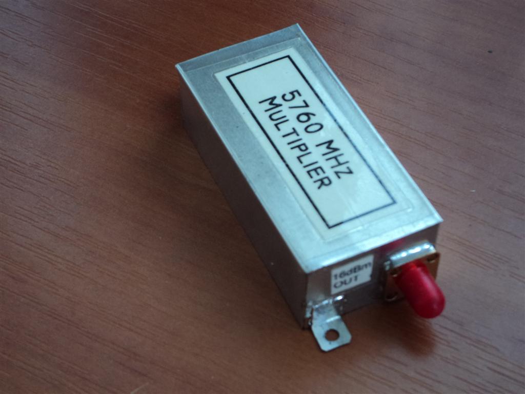
was programmed to 1776MHz. The 13dBm output was attenuated with the 7db attenuator to safely drive the 3x multiplier box producing some 15dBm of the signal @ 5328MHz. Again 7db attenuator between the multiplier and mixer to bring the signal to the required mixer level. At the same time the mixer was very happy to "see" the 50 ohms impedance at any port. For this experiment i choose the IF 432MHz, but much better will be 434 or higher. Not more than 0dBm is required on the mixer IF port, so the 27dBm (500mW) signal from the FT-817d was reduced with the 26db attenuator at the sequencer board. Sequencer is also switching the power for the MMICs in the transverter as well as the power for the coaxial relay at the output. RF sensing and PTT ports insuring high protection. If the coaxial relay or RF electronic switch is not available we can use two separate antennas for the RX and TX. With this arrangement the setup is ready for the smoke test and initial qso testing. The output power is low, not reaching not even 1mW and the conversion gain is also poor just a few db so some extra amplification is required for serious work. 


Good LNA will lower the noise figure and improve the conversion gain and on the other side a few MMICs on the TX side will give us pleasure to work some distant stations. Just for the test I add another SNA-586 on the TX side bringing the signal up to the 3dBm. Not much, but at the same time I add another pipe cap filter between the MMIC blocks to reach the cleaner signal at the output. Result can be seen at the video. The same approach can be used to build the transverter for the other microwave bands, so no excuse for the low activity at the microwave bands. 

So "Use them or lose them"


Wednesday, December 5, 2012

24 GHz transverter update

As I received a few queries regarding the transverter here is the update on done so far. I make some small modifications but nothing that is diverting from the original idea. I did have a big problems with the YIG PLL oscillator MTS1500 which was not working properly. I discovered that the YIG inside the whole unit is faulty, can not be locked neither controlled properly. After so many time devoted to this unit I quit and order the other YIG PLL oscillator DFS-1201 which is working as required, immediately after first start. More over I program two frequencies so the same unit can be used aloso as the LO for the 47GHz operation.

Briefly, here we have a DFS-1201 YIG PLL programmed for L.O./2 frequency to suit the 436MHz IF. DFS-1201 is controlled via the small PCB with the PIC microcontroler (directly on the DFS-1201 connector) where 2 programmed frequencies are available. The output signal is 14dBm and splited in two for upconverter and downconverter. No waveguide relay as mentioned previously, isolator is good enough to protect the downconverter from the 300mW which can produce the TRW upconverter.
The bottom PCB is switching the voltages for the units and acting as a small sequencer together with the IF attenuator and switching.
Power supply boards with the voltage stabilisers are attached to the left/right walls of the plastic housing.


The antenna is attached directly to the third isolator port through the short peace of the WR-42 flexible waveguide. The antenna is not so big and the radom has been dismantled to make this system light and easy for operating. Even not so big the antenna is quite sharp and careful pointing is required.


Some initial test were performed and overall feeling is that the transverter perform very good. The RX NF is very good and the YIG PLL stability after initial warming up of 5 minutes is excellent. Circulator instead of  relay seems to be a very handy because no headache and fear to burn the downconverter front end. No "smart" sequencing is required and loss are reduced to the minimum.
Present ODX is 168.5 km LOS qso during the summer with the humidity close to 90% over the sea path. Winter should be the right time to gain this distance.


73 and CU on 24GHz

Monday, November 12, 2012

W1GHZ cheap 3cm beacon board

Some time ago besides some other PCB's I ordered also the board for the simple 3cm beacon oscillator project from Paul, W1GHZ. The price was really affordable, and you never know when you will need some simple multiplier project like this. The latest, I heard that he is running with stock low of this board, so this means that people are building this stuff more and more. On the other side, not so many feedback on the web regarding the results obtained from this simple multiplier leaving idea that all this projects are working perfect with no problems or they are not working at all and people are giving up without an extra effort to tune properly this interesting approach to old fashioned multiplier idea.

So here it is, completed and tuned multiplier for 10368MHz. Of course, I did make some small modifications to get the best results from this board, at the end it is working. I saw that Paul published the update on this project, but maybe somebody will find my hints useful too. 
The first thing that can be noticed, my tuning screws are quite long, this is not necessary. I did use the same project for some other final frequencies (11808MHz) and I left the screws long enough also for the lower frequencies. The size of the screws: M4 brass for the first (3.5GHz) pipe cap and M3 brass for the other two (10GHz) pipe caps.
Secondly, I did use 9V power supply, instead of 8V. The only reason was the 9V voltage regulator that was handy for me. All MMIC bias resistors are modified to get the best results with 9V.  As there is enough place on the board, I have two resistors in series for each MMIC stage. This way I can easily tune the bias current and the dissipation on resistor is lower, even I am using 1208 SMD bias resistors.
About MMICs, I mount 3x SNA-286 and 2x NLB-310. I went through the data sheets quickly, and I noticed that ERA-1 is quite poor for the 10GHz and decide to use NLB-310. I don't know how Paul manage to get the 11dBm from ERA-1 on 10GHz, but this is not option not even in the data sheet :-)

So, this are all mods. done from my side regarding the original approach. Let's start with tuning...

I have to said that without Spectrum analyzer not reading the Paul's advice, tuning this multiplier can be quite confusing. So, at least any kind of power detector able to detect -10dBm @ 10GHz is a "must" to reach the final result. For the signal generator, I did use the handy Si-4133 generator where i have programmed 16 well known microwave frequencies. 1152MHz and 5dBm is what we need. 
The first pipe cap should be tuned  to x3 = 3456MHz. This should not be a big problem because of the size of the pipe cap that does not allow to tune to the 2nd harmonic frequency. With the screw completely inside, backing the screw a few turns out the strong signal / power peak will be present at certain point at the first SMA tuning point. At this point you are at 3456MHz, all what we need from the first two MMICs and big pipe cap. Backing the screw more out you will reach another peak of the signal, almost the same strength, this is x4 = 4608MHz. If you have a sensitive power meter or detector, backing the screw almost completely out of the pipe cap you can observe some weak peak also on the x5 = 5760MHz frequency. So, this pipe cap can be tuned to 3 different frequencies, our goal is to tune to the lower (first) one.
This step was quite easy, the next one will require more precision and patience. The two 1/2 pipe caps should be tuned to 10368MHz. They are to small to be tuned to the x2 =6912MHz and they are too big to be tuned to x4 = 13824MHz so the only possibility is to tune them to x3 = 10368MHz. With the M3 screws completely inside slowly backing them, some where in the middle of the pipe cap you will notice the power peak at the output SMA. You will need to tune both pipe caps parallel to reach this point. Once you reach the peak, tune the both screws for the maximum output signal. This should bring you on the 10368MHz.

Looking nice, well more about this later :-)
Following this procedure the power I get on the 10GHz was only 0dBm, not even. The first thought was, where the f... I lost the 10dBm?? Driving the multiplier with the different power levels I found the +7dBm  @ 1152MHz gave the best output (+1dBm). But this is still far away from +11dBm...
I start to play with the first MMIC (SNA-286) bias resistors, and there was a nice improvement. I had to increase the resistor almost double to squeeze the maximum from this first multiplier stage. The output power went easily to +5dBm. I thought that same procedure with tuning the third SNA-286 bias multiplier will bring up the output power to desired +10dBm but this was not the case. Changing the bias did not bring any better results. Maybe SNA-286 are not so good in producing the harmonics at higher frequencies??
So, for the moment I stopped here, +5dBm @ 10368MHz is good enough for me, but for sure I will investigate the difference between the ERA-2, SNA-286 and some other MMIC candidates in producing high reach harmonics above 10GHz.

Let's go back to a nice looking signal shape from the picture before. Really nice ha? OK, there is another (fuzzy) shot of the Spectrum analyzer screen.

Not so perfect, ha? Well, believe it or not, this is the same signal from the previous picture. So where is the catch? To simply explain, I will compare this with the Miss universe competition :-) Looking from the balcony all those girls looking nice, but coming closer we can see that some of them are looking not so good as from the balcony. Same here, if you use the span of 100MHz you will get the first picture, if you use the span on the S.A. of 1MHz you can  get the 2nd, more realistic picture.
Well, this have nothing to do with the multiplier, but just want to give you an idea how Si-4133 signal looks after x9 multiplication. I want to gain that my Si-4133 oscillator is using the good quality Isotemp double oven 10MHz reference oscillator, so imagine how the signal will look using the cheap 10MHz canned oscillator.
I get the nice phase noise comparison measurement chart made recently on the MUD 2012 meeting compiled from Paul, W1GHZ. So all credits goes to him and the guy who measure it. Nothing more to add...


At the end, just a few ideas where to use this multiplier, of course the first idea will be a simple 3cm signal beacon source. I did use the same to generate the 11808MHz signal for one of my 24GHz transverters. You can hook up also the Comtech ATV TX tuned to 1161 MHz to reach 10450MHz. Driving this multiplier with the 720MHz can result with the output of 10800MHz which can be a simple L.O. solution for the 10368MHz transverter with the I.F. 432MHz (LSB). So many solutions for the simple multiplier.

By the way, if you manage to reach +11dBm of output power, let me know...


Friday, November 2, 2012

Simple 6cm - 5760 MHz beacon


This is just another simple beacon for 6cm band that came out as a result of raining afternoon and a desk full of various microwave components. Of course, this can be done on many different ways but I choose to use the parts that are cheap and available to every microwave builder. As most of my designs this project is also modular where every component can be replaced with some other, resulting maybe better, maybe worst performance but at the end the output signal level will be within the range of a few dB of difference.


This is a block diagram of the beacon oscillator from my scrapbook. After so many simple project I start to take a notes with at least few measurements so If I need these data later, they are always here in the notebook. Th PC is nice but notebook is better.
So no detail electrical diagram this time because all blocks are explained already through my previous designs. The beacon is built around well known S53MV crystal oscillator used in his beacons or ZIF microwave radios. The 720MHz signal is attenuated to a level of approx. 5dBm to drive more efficiently the 6cm multiplier explained on my blog. As we are dealing with the multiplying factor  of 8, not much of the signal is left at the required frequency of 5760 MHz. This signal is amplified with a two MMICs blocks, the first one withe the NLB-310 and the second one with the SNA-586. The output power is around 10dBm or 10mW. The filter is optional, but recommended, reducing the output power to 8dbm+


Going from the left, the 720MHz oscillator (still not screened) is starting with the 20MHz crystal. This is a common value where also cheap computer grade crystals can work. There is a tuning inductor and trimmer capacitor with possibility to tune desired frequency, in my case at the beginning of the band, but leaving enough room for EME operators. after the multiplying chain (x3 x3 x2 x2) we end up with decent level of 11dbm+ for the next stage.

Maximum allowed input level for the multiplier is +10dbm, so attenuator was required in between. Playing with the attenuator values I found that the 6db attenuator will give the best results, higher output of the multiplier for the 8x multiplying factor.

The multiplier was driven with the 5dBm of the signal for the best performance. Even better results are possible by changing the value of the bias resistor in the first MMIC multiplier stage. Usually higher resistor value will give up to 3dB better output signal for desired input frequency. I did not play with that in this project, so there is room for improvement. I got -9dBm of signal after the multiplier.


MMIC blocks are simple and cheap and they have a decent gain. I choose the two different MMICs to see how they perform at 6GHz. The first one with NLB-310 is working very nice with the 11dB of the gain producing almost +2dBm of the signal. The second one, SNA-586 gives another push to +10dBm with the gain of just litle bite more than 8dB on 6 GHz.

The filter is optional but can be very useful if you plan to use this beacon on remote high location. 3/4 pipe cap filter can be the easiest solution. Just tune the filter to maximum signal and this is enough. Place the filter between the MMICs to isolate them with the I.L. of the filter. After initial attempt my pipe cap filter was inserting 4dB of loss, a bit high. Then after fine tuning I was able to reduce the I.L. to only 1.6dB @ 5760MHz. Inserting the filter the output drops to +8dBm.

The last component (gray)that can be seen is directional coupler. This is not a part of the beacon oscillator. It was used just to simultaneously monitor the signal on the frequency  counter and the spectrum analyzer.


This is the core of the 6cm beacon. The rest of the parts that are required are beacon keyer, power supply and the antenna. The keyer is already explained on the blog, where multiplier stage should be keyed with the positive voltage. Power supply can be anything that can give you 500mA @ 13,6V. The antenna type depend on the requirement, simple horn or slotted waveguide can be a solution or if you want to go really cheap and simple, a simple vertical Wi-Fi 5.7GHz band can be good also but vertical polarization will produce less signal for H-pol weak signal users. For a home use, this is the best-buy option.

Sunday, October 28, 2012

Modification TOKO 5HW-1150-45F filter for 23cm band

I have this nice and small (and expensive) helical filter in my drawer for some time. Looking the TOKO filter data-sheet this is very nice filter for the 1152 MHz local oscillator project, but I want to use the same one in my 23cm transverter, for filtering 1296 MHz. The data-sheet states that it is not possible to tune to the desired frequency. Of course, there is another filter covering that particular part of the band but my drawer is not TOKO store :-)


 Going back to the data-sheet... It is clear that this is double tuned helix type filter, center frequency 1195 MHz with the coupling done through the window inside the metal shield. The connection diagram (F connections) in the data-sheet does not give a real situation of the helix inside the shield. From the diagram we can see that there is a helix between the hot end and the ground connection and a small part of the helix continuing after the hot end pin connection. Basically, the idea is just to short the helix to bring the resonance higher using cut and try method, but following the diagram there is nothing much to cut on F version.

On the other side I got the hint from Goran AD6IW that he make the mods. on the same filter very easy and simple and this should work, so this was good reason to try and see what is going on inside the "mystery helix".


Do not be afraid, this is going to be very quick and simple modification. You do not need not even a soldering iron, just a small sharp cutter and a small flat screwdriver. Each of the helix is secured inside the housing with the 4 dents, 2 on each side. Using a tip of a sharp flat screwdriver bent vertically all 4 dents to free the brown helix former. Pull out the the  helix former, and you will have the same situation as from the following photo:


You probably ask yourself the same question I ask myself too, WTF is worth 20$ inside this helix filter ?! Do not look and search for any other parts inside the metal shield, there is nothing else inside except the tuning screw :-)

First thing that you may notice is that the real situation is not the same as on the diagram. The "helix coil" between the hot end and the ground pin is just a bridge from one pin to another, no any helix turns at all, as showed on the diagram. The helix is then extending from the live end pin around the coil former exactly 5 turns. What we need to do is just short the helix to bring the center resonance around the 1296 MHz. Cut and try method was the simplest one and gave excellent result. The helix is soldered on one end to the connecting pin and the other free end is just bended wire inside the gap of the coil former. To bring the resonance up, simply cut and remove just 1/4 of the last wire turn from the helix using the tip of the sharp cutter. The wire is stiff enough to stay on the coil former, but if you feel that the helix will be unwound secure the helix with the drop of super glue. I did not use this method because I didn't know what effect can cause the glue to the coil resonance and Q factor (if any?).
Use the same procedure for the other helix in the filter. After all, insert the coil formers back to the shield and secure them with the same 4 dents from the beginning of the modification.


So that's it, just a 1/4 turn shorter helix solved the problem and the filter is tuning smoothly to the 1296 MHz with almost identical response curve. I did check the filter directly soldering the SMA connector to the live pin and ground shorting the ground pin and shield. This was much simpler than soldering the filter on the special PCB. The proper way of tuning will be using the network analyzer but this is not so common among the HAM experimenters so simple generator, oscillator on 1296 MHz and LNB diode detector can do the job also.


Finally, check this cheap and dirty approach, the LNB IF MMICs (C1H & C1E) board with the modified TOKO filter. -13dB of input gives out filtered +12dB of signal on 1296 MHz. You can use this board both way, for RX & TX, so simple, the half of the 23cm transverter is already here :-)

Tuesday, July 10, 2012

5.7 GHz with Microwave LEGO bricks

Microwave lego bricks for 5.7 Ghz

Just downconverter part:

L.O. = Si4133 pll Fout=1776 MHz  (10Mhz reference triple oven)
Multiplier x3 = SNA386 + SNA586
I.F. = 432 MHz

1st brick = MGA86576
2nd brick = Pipe Cap filter 5.7 Ghz
3rd brick = MGA86563
4th brick= Mixer SKY-60LH


Monday, June 25, 2012

Simple LNB diode marker (harmonic multiplier)

Based on G3PHO marker generator.


Double LNB mixer diode can be used as well, but only one diode from the pair. Leave the third pin NC in the air.


Tested up to 24GHz, check the video, 1152MHz / 13dBm input = 10368MHz out


And the second one, 1336MHz / 13dBm input = 24048 MHz out (18th harmonic!!!)


If more signal required or wider range, place the diode across the Vivaldi type UWB antenna....

Thursday, June 7, 2012

6cm NO tune multiplier

This is very simple multiplier which can give you possibility to simply enter the 6cm band at the same time not spending the big $$. The idea was to make a simple multiplier where no tuning is required, just Plug and Pray :-) This approach is very handy for the hams with the basic measuring equipment and counters that can measure up to 1.3 GHz (with old TV prescalers) or maybe for the guys able to buy cheap 2.8 GHz counters from China through E-bay. Measuring higher frequencies with the commercial counters require more expensive equipment and most of the home brewers are stuck on 13cm band. This project is perfect not just for them, but for all looking for a cheap unit working on the 6cm band.

As can be seen from the photo, cheap means using double side FR-4 laminate, so no fancy Rogers, Teflon, alumina etc. Only two active devices, cheap and e-bay available MMICs, a few SMD resistors and capacitors and one voltage regulator. Of course, microstrip filter is printed on the PCB. This should be cheap enough and still working ! The design is quite old fashioned already proved where saturated active device produce output rich with the harmonics. The required harmonic is "extracted" through the filter and amplified with the second active device. This is the all "magic" going around all similar multipliers that you may have seen up to now. The difference may be only in the type of active device used, type of filter and quality of the PCB. The theory of operation is more or less the same.


Both active devices are MMIC from Sirenza. The first one (multiplier) is SNA-386 and the second one (amplifier) is SNA-586. Instead of Sirenza someone can use the ERA-3 and ERA-5 devices with the very close results. I choose the Sirenza because they are cheaper and easy available from the E-bay and on the other side they perform a little bit better then ERA substitutes. It is important not to overdrive the first MMIC (SNA-386) where you can easily blow-up the MMIC if applying more than +10dBm (10mW) of the RF power. To be honest, 7dBm (5mW) is more than enough for successful operation and multiplier is working even with the 2mW drive.
In case that you have excess input power you can always use the attenuator at the input. There is enough room left at the input, just before the 1st MMIC to accommodate simple Pi type attenuator made from the SMD resistors. Of course, more expensive SMA attenuator can be used instead.
The PCB filter is the exact copy of the S53MV printed filter used in the ZIF transceivers where good results are obtained regarding band-pass, I.L. and band-stop characteristics. The filter is cheap enough, easy to fabricate and will satisfy most of our needs on 6cm band. 


The PCB is fabricated using the double side FR-4 0.8mm laminate, dimensions 30x65mm. The PCB layout is using S53MV solutions, like band-stop filter (DC bias) and via design technique. Up to now I did not find a better solution that can be done at home lab. For the via, just drill the hole diameter 3.2mm. Cover the hole and solder the peace of brass or copper foil from the PCB ground side. Fill up the hole with the solder. I did try to calculate the inductance and capacitance of such made "via" and the results are very good. As a matter of fact I notice that some commercially made microwave equipment is using similar approach where active component is soldered with the ground pins to the small peace of brass inserted in the PCB slot. On the other side of the brass plate there is M2 thread extending, allowing to secure and screw the brass to the heat-sink or conductive ground pad.


The left PCB on the photo is 117MHz to 702MHz multiplier used later with the 6cm no tune multiplier. The PCB's are fabricated using the tone transfer method. The filter traces are still sharp enough, no problems with that. Of course, the filter on the FR-4 laminate will radiate but we need to live with that if we want to use this simple and cheap approach. Most of the components are soldered on the signal layer side except the voltage regulator with associated capacitors soldered straight on the pins. More over, instead of using 1nF pass through capacitors I am running just a peace of wire through the PCB. I cut the small squares using the x-acto knife on the PCB ground side, just around the place where through wire is soldered. From the same pad 1nF SMD capacitors are soldered to ground layer. Insulated wire is connecting the voltage regulator with the through wire pads for MMIC supply.


Proper MMIC bias was done using the serial pair of SMD resistors. This way the power dissipation from the resistors was split preventing overheating and burning the SMD bias resistors. I am using 1206 (power rating 0.25 watt) size resistors for the bias. SNA-386 MMIC bias can be done even with the 0805 size (power rating 0.125 watt) but SNA-586 must be done with the 1206 size resistors. Depending of the multiplying factor, somebody would like to play with the bias voltage to obtain the best results and higher output. It is much easier and safe to play with combination of two resistors in bias than just one.


After soldering all SMD components, it is important to clean all excess flux from the PCB, specially around the MMIC. This will give you some more power at the end. As this is no tune project, simple power on should be enough for proper operation, but if you want to be sure that there will be no smoke after some time you can always perform a small check. First power on can be done with no input drive and output terminated with the 50 ohms load. Apply the power through the milliampermetar which should read 100mA (+/- 10mA). You can also check to bias voltage and current on each MMIC. When you are sure that all is according to data sheet specs. you can add some drive to the multiplier (stay bellow 10dBm!!). The current will stay almost the same. If you have any means of measuring the output power you can notice that there should be at least 10dBm up to 16dBm on the 5.7 GHz depending the applied input power and multiplying factor.
I did not play with the bias resistors to get the best output results because this can work with some frequencies but not for all. Anyhow there is a plenty output power for all purposes.


No sign of self oscillations were noted, the multiplier perform very stable even not screened. After all the PCB can be screened in the small metal sheet box same size as the PCB and 20mm high. The PCB is positioned some 5mm from the bottom leaving space for the 9V regulator soldered to the ground PCB layer. Then the ground layer is soldered for the metal housing all around. No sign of strange oscillations nor the box resonance observed at all despite the high MMIC gain. S53MV ground via system is proved to be the best and cheap way in the home brew desk projects.

At the end, where we can use this simple multiplier. Here are some of the examples:

ATV extender 1.15 GHz to 5.75 GHz
If you are ATV fan this can be the easiest way to reach the ATV at the 5.7 GHz. The Comtech ATV tx for the 23cm can be used with no problems. The frequency can be tuned down to 1150 MHz and after x5 multiplying we have 5750 MHz at the output. Observe the SMA attenuator!! Do not drive the multiplier directly from the Comtech module.


6cm signal generator
The same Comtech unit can be used for the 6cm signal generator. This is the cheap way to generate the required signal for tuning the filters or checking the RL on antennas. All you need is already mentioned Comtech 23cm module controlled with the PIC controller and LCD display. The range from 5-6 GHz is no problem at all. IK8UIF offer handy Comtech controller where LCD screen can be programmed to show x5 frequency already.


5616 MHz L.O. for the 6cm transverter use
For all building the 6cm transverter this can be easy way to multiply the 702 MHz signal from the OCXO to required 5616 MHz. This was the lower frequency that I apply to the multiplier that produce enough output level without an extra amplifier at the end.


Mini beacon 5.7 GHz
If you need a local mini beacon for testing the 6cm equipment this can be more than enough. Applying well known 1152 MHz signal at the input will result with the 5760 MHz signal at the output. Adding some 6cm antenna the range will be improved up to few km LOS.


Beacon 5.7 GHz
If beacon for 5.7 GHz is required, this can be part of it. The 1152 MHz oscillator is Synthesised Si-4133 with the OCXO 10MHz reference. The multiplier is producing the required 5760 MHz signal. To have the proper identification, the multiplier was switched through the PIC beacon keyer. The output frequency is stable and no chirp observed at all. Check the video:


So this is all. If you are already thinking of 10 GHz no tune multiplier, yes it can be done. I do have some nice results using the modified LNB PCB's with the new NLB-310 MMIC's. Maybe in some next post.......

Wednesday, May 23, 2012

Omnidirectional H-pol antenna for X-band

This is funny..........
I've been looking this unit for last ten to fifteen years, well from the very first moment that SART (search and rescue radar transponder) was introduced. More over I am checking this unit every week for the proper operation, not one, but six units and I know very well how it work and the operating frequency. For us, it is not important how it work, but I can mention that when operative the SART is in the stand by mode, only the X-band (9.2-9.5 GHz) receiver is working waiting to be triggered with the ship's radar signal to invoke the SART transmitter covering complete band with series of pulses creating on the radar screen 12 dots from the current position to the radar location. SART is using the same antenna inside the plastic housing for RX/TX operation. What can be interesting for us is the antenna!!


Why antenna? Several years I was looking for an efficient omnidirectional 3cm antenna for ATV or beacon purposes. Present double slot waveguide antenna is showing that omnidirectional diagram is far from perfect with the directions where the signal is lower from 3-5 dB comparing to the other directions. It means perfect picture on one side and weak or now picture at all on the other side at the same time. During all this years it never come to my mind to check what kind of antenna is inside the unit and finally - BINGO! Well, it came the time for periodical battery pack change where unit should be dismantled, otherwise the antenna will remained undiscovered :-). This is what was found inside:


Quick first look and I thought WTF?? Stacked slot on the round waveguide, this can not work, there should be some catch for sure, Jotron is serious company = no f***ups there, let's examine this antenna. First thing that I notice was the diameter with 31 mm. Hmm, this is odd ?? Then, vertically stacked slot with coupling pin extending inside the hollow, OK this got some sense and at the end SMA connector at the bottom. Thinking: what kind of mechanism and mode for operation is using this antenna?

Still thinking :-)


Let's stop thinking and call the antenna guru, this should save me a plenty of time going through the endless PDF antenna books and magnetics theory. The answer was prompt and direct to the point: this antenna is using the cavity properties and mechanism for propagating the energy inside the hollow.
OK - mystery solved, so simple :-)
Following the cavity properties here we have a hollow metal closed structure. This closed resonator confine the electromagnetic fields. The electromagnetic fields inside the cavity are excited via the quarter wave length probe at the bottom through the SMA connection. The electromagnetic energy is "stored" inside the low loss cavity affected in small part by losses in cavity walls. The energy is coupled through the quarter wave length probes penetrating inside the resonator from the center of the each slot. Opposite to the dipole the electric and magnetic fields are interchanged in the half wavelength slot. The electric field is build up across the narrow dimensions of the slot which result that vertical slot is radiating the horizontal polarization. Equally spaced slots at the face of the resonator will result with omnidirectional radiation pattern. This way we manage to have omnidirectional pattern with the horizontal polarization. More gain is achieved by stacking the slots in the vertical plane.


So here we have a weak photo, sorry for that, but $$$ mobile phone digital camera can not do better :-) of detail where the coupling probes are extending inside the hollow. They are about quarter wave long, same as the SMA launching probe. The measures from the design down are accurate within 0,5mm. I use just a handy ruler just to measure the antenna for those who wish to recalculate the antenna for some other bands.

Reverse engineering = dismantling perfectly working unit with idea to do something but no will to do anything :-)
If you have done something like this, let me know, it will be interesting to see some directivity pattern.