Thursday, June 7, 2012

6cm NO tune multiplier

This is very simple multiplier which can give you possibility to simply enter the 6cm band at the same time not spending the big $$. The idea was to make a simple multiplier where no tuning is required, just Plug and Pray :-) This approach is very handy for the hams with the basic measuring equipment and counters that can measure up to 1.3 GHz (with old TV prescalers) or maybe for the guys able to buy cheap 2.8 GHz counters from China through E-bay. Measuring higher frequencies with the commercial counters require more expensive equipment and most of the home brewers are stuck on 13cm band. This project is perfect not just for them, but for all looking for a cheap unit working on the 6cm band.

As can be seen from the photo, cheap means using double side FR-4 laminate, so no fancy Rogers, Teflon, alumina etc. Only two active devices, cheap and e-bay available MMICs, a few SMD resistors and capacitors and one voltage regulator. Of course, microstrip filter is printed on the PCB. This should be cheap enough and still working ! The design is quite old fashioned already proved where saturated active device produce output rich with the harmonics. The required harmonic is "extracted" through the filter and amplified with the second active device. This is the all "magic" going around all similar multipliers that you may have seen up to now. The difference may be only in the type of active device used, type of filter and quality of the PCB. The theory of operation is more or less the same.


Both active devices are MMIC from Sirenza. The first one (multiplier) is SNA-386 and the second one (amplifier) is SNA-586. Instead of Sirenza someone can use the ERA-3 and ERA-5 devices with the very close results. I choose the Sirenza because they are cheaper and easy available from the E-bay and on the other side they perform a little bit better then ERA substitutes. It is important not to overdrive the first MMIC (SNA-386) where you can easily blow-up the MMIC if applying more than +10dBm (10mW) of the RF power. To be honest, 7dBm (5mW) is more than enough for successful operation and multiplier is working even with the 2mW drive.
In case that you have excess input power you can always use the attenuator at the input. There is enough room left at the input, just before the 1st MMIC to accommodate simple Pi type attenuator made from the SMD resistors. Of course, more expensive SMA attenuator can be used instead.
The PCB filter is the exact copy of the S53MV printed filter used in the ZIF transceivers where good results are obtained regarding band-pass, I.L. and band-stop characteristics. The filter is cheap enough, easy to fabricate and will satisfy most of our needs on 6cm band. 


The PCB is fabricated using the double side FR-4 0.8mm laminate, dimensions 30x65mm. The PCB layout is using S53MV solutions, like band-stop filter (DC bias) and via design technique. Up to now I did not find a better solution that can be done at home lab. For the via, just drill the hole diameter 3.2mm. Cover the hole and solder the peace of brass or copper foil from the PCB ground side. Fill up the hole with the solder. I did try to calculate the inductance and capacitance of such made "via" and the results are very good. As a matter of fact I notice that some commercially made microwave equipment is using similar approach where active component is soldered with the ground pins to the small peace of brass inserted in the PCB slot. On the other side of the brass plate there is M2 thread extending, allowing to secure and screw the brass to the heat-sink or conductive ground pad.


The left PCB on the photo is 117MHz to 702MHz multiplier used later with the 6cm no tune multiplier. The PCB's are fabricated using the tone transfer method. The filter traces are still sharp enough, no problems with that. Of course, the filter on the FR-4 laminate will radiate but we need to live with that if we want to use this simple and cheap approach. Most of the components are soldered on the signal layer side except the voltage regulator with associated capacitors soldered straight on the pins. More over, instead of using 1nF pass through capacitors I am running just a peace of wire through the PCB. I cut the small squares using the x-acto knife on the PCB ground side, just around the place where through wire is soldered. From the same pad 1nF SMD capacitors are soldered to ground layer. Insulated wire is connecting the voltage regulator with the through wire pads for MMIC supply.


Proper MMIC bias was done using the serial pair of SMD resistors. This way the power dissipation from the resistors was split preventing overheating and burning the SMD bias resistors. I am using 1206 (power rating 0.25 watt) size resistors for the bias. SNA-386 MMIC bias can be done even with the 0805 size (power rating 0.125 watt) but SNA-586 must be done with the 1206 size resistors. Depending of the multiplying factor, somebody would like to play with the bias voltage to obtain the best results and higher output. It is much easier and safe to play with combination of two resistors in bias than just one.


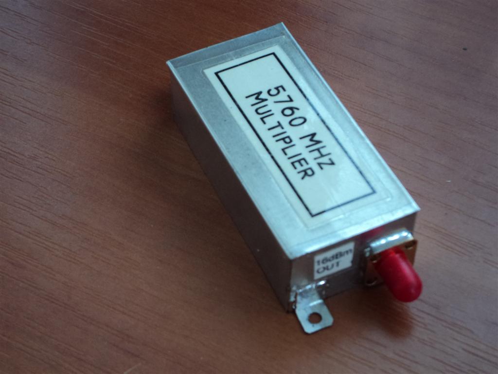
After soldering all SMD components, it is important to clean all excess flux from the PCB, specially around the MMIC. This will give you some more power at the end. As this is no tune project, simple power on should be enough for proper operation, but if you want to be sure that there will be no smoke after some time you can always perform a small check. First power on can be done with no input drive and output terminated with the 50 ohms load. Apply the power through the milliampermetar which should read 100mA (+/- 10mA). You can also check to bias voltage and current on each MMIC. When you are sure that all is according to data sheet specs. you can add some drive to the multiplier (stay bellow 10dBm!!). The current will stay almost the same. If you have any means of measuring the output power you can notice that there should be at least 10dBm up to 16dBm on the 5.7 GHz depending the applied input power and multiplying factor.
I did not play with the bias resistors to get the best output results because this can work with some frequencies but not for all. Anyhow there is a plenty output power for all purposes.


No sign of self oscillations were noted, the multiplier perform very stable even not screened. After all the PCB can be screened in the small metal sheet box same size as the PCB and 20mm high. The PCB is positioned some 5mm from the bottom leaving space for the 9V regulator soldered to the ground PCB layer. Then the ground layer is soldered for the metal housing all around. No sign of strange oscillations nor the box resonance observed at all despite the high MMIC gain. S53MV ground via system is proved to be the best and cheap way in the home brew desk projects.

At the end, where we can use this simple multiplier. Here are some of the examples:

ATV extender 1.15 GHz to 5.75 GHz
If you are ATV fan this can be the easiest way to reach the ATV at the 5.7 GHz. The Comtech ATV tx for the 23cm can be used with no problems. The frequency can be tuned down to 1150 MHz and after x5 multiplying we have 5750 MHz at the output. Observe the SMA attenuator!! Do not drive the multiplier directly from the Comtech module.


6cm signal generator
The same Comtech unit can be used for the 6cm signal generator. This is the cheap way to generate the required signal for tuning the filters or checking the RL on antennas. All you need is already mentioned Comtech 23cm module controlled with the PIC controller and LCD display. The range from 5-6 GHz is no problem at all. IK8UIF offer handy Comtech controller where LCD screen can be programmed to show x5 frequency already.


5616 MHz L.O. for the 6cm transverter use
For all building the 6cm transverter this can be easy way to multiply the 702 MHz signal from the OCXO to required 5616 MHz. This was the lower frequency that I apply to the multiplier that produce enough output level without an extra amplifier at the end.


Mini beacon 5.7 GHz
If you need a local mini beacon for testing the 6cm equipment this can be more than enough. Applying well known 1152 MHz signal at the input will result with the 5760 MHz signal at the output. Adding some 6cm antenna the range will be improved up to few km LOS.


Beacon 5.7 GHz
If beacon for 5.7 GHz is required, this can be part of it. The 1152 MHz oscillator is Synthesised Si-4133 with the OCXO 10MHz reference. The multiplier is producing the required 5760 MHz signal. To have the proper identification, the multiplier was switched through the PIC beacon keyer. The output frequency is stable and no chirp observed at all. Check the video:


So this is all. If you are already thinking of 10 GHz no tune multiplier, yes it can be done. I do have some nice results using the modified LNB PCB's with the new NLB-310 MMIC's. Maybe in some next post.......

Wednesday, May 23, 2012

Omnidirectional H-pol antenna for X-band

This is funny..........
I've been looking this unit for last ten to fifteen years, well from the very first moment that SART (search and rescue radar transponder) was introduced. More over I am checking this unit every week for the proper operation, not one, but six units and I know very well how it work and the operating frequency. For us, it is not important how it work, but I can mention that when operative the SART is in the stand by mode, only the X-band (9.2-9.5 GHz) receiver is working waiting to be triggered with the ship's radar signal to invoke the SART transmitter covering complete band with series of pulses creating on the radar screen 12 dots from the current position to the radar location. SART is using the same antenna inside the plastic housing for RX/TX operation. What can be interesting for us is the antenna!!


Why antenna? Several years I was looking for an efficient omnidirectional 3cm antenna for ATV or beacon purposes. Present double slot waveguide antenna is showing that omnidirectional diagram is far from perfect with the directions where the signal is lower from 3-5 dB comparing to the other directions. It means perfect picture on one side and weak or now picture at all on the other side at the same time. During all this years it never come to my mind to check what kind of antenna is inside the unit and finally - BINGO! Well, it came the time for periodical battery pack change where unit should be dismantled, otherwise the antenna will remained undiscovered :-). This is what was found inside:


Quick first look and I thought WTF?? Stacked slot on the round waveguide, this can not work, there should be some catch for sure, Jotron is serious company = no f***ups there, let's examine this antenna. First thing that I notice was the diameter with 31 mm. Hmm, this is odd ?? Then, vertically stacked slot with coupling pin extending inside the hollow, OK this got some sense and at the end SMA connector at the bottom. Thinking: what kind of mechanism and mode for operation is using this antenna?

Still thinking :-)


Let's stop thinking and call the antenna guru, this should save me a plenty of time going through the endless PDF antenna books and magnetics theory. The answer was prompt and direct to the point: this antenna is using the cavity properties and mechanism for propagating the energy inside the hollow.
OK - mystery solved, so simple :-)
Following the cavity properties here we have a hollow metal closed structure. This closed resonator confine the electromagnetic fields. The electromagnetic fields inside the cavity are excited via the quarter wave length probe at the bottom through the SMA connection. The electromagnetic energy is "stored" inside the low loss cavity affected in small part by losses in cavity walls. The energy is coupled through the quarter wave length probes penetrating inside the resonator from the center of the each slot. Opposite to the dipole the electric and magnetic fields are interchanged in the half wavelength slot. The electric field is build up across the narrow dimensions of the slot which result that vertical slot is radiating the horizontal polarization. Equally spaced slots at the face of the resonator will result with omnidirectional radiation pattern. This way we manage to have omnidirectional pattern with the horizontal polarization. More gain is achieved by stacking the slots in the vertical plane.


So here we have a weak photo, sorry for that, but $$$ mobile phone digital camera can not do better :-) of detail where the coupling probes are extending inside the hollow. They are about quarter wave long, same as the SMA launching probe. The measures from the design down are accurate within 0,5mm. I use just a handy ruler just to measure the antenna for those who wish to recalculate the antenna for some other bands.

Reverse engineering = dismantling perfectly working unit with idea to do something but no will to do anything :-)
If you have done something like this, let me know, it will be interesting to see some directivity pattern.

Thursday, October 13, 2011

W1GHZ rover transverter for the 3400 MHz - EU band coverage

And finally, the 9cm band cheap rover W1GHZ transverter for the EU band coverage is also finished. As already mentioned in the 13cm transverter post, the band coverage with the original L.O. does not permit operation on the EU portion of the band, in this case 3400-3410 MHz. Some modifications were required and here we go, another easy and cheap way to start with the new band not spending the big bucks. Not yet in the proper housing but even without it no unwanted oscillations or products observed.


Looking from the left side there is a small power amplifier with the AH-102A and a peace of heatsink from the old PC switching power supply followed by the well known W1GHZ transverter board for the 9cm band with the 1/2" pipecap filters. As the transverter will be used at the Europe with the different 9cm band allocation the original 720 MHz local oscillator does not help in this case. Separate local oscillator, S53MV style, already used in the 13cm transverter will be used but with the different output frequency. At the end on the right side there is a so called "sequencer" taking care of switching power and everything that have to be switched in the transverter.


I will start from the oscillator this time. After the multiplying (5x) the original 720 MHz oscillator should give us the 3600 MHz signal on the transverter board after the pipecaps. Mixing with the 144 MHz (LSB) we should reach 3456 MHz. If we want to use this idea in the EU we should have a 200 MHz I.F. radio which is not convenient at all. Going back to the well proved practice, the S53MV oscillator used in the ZIF microwave radios was a cheap and flexible solution offering many multiplying schemes to reach required frequency. For the I.F. I choose the 70cm band where we have 10 MHz (from 430-440 MHz) comparing to the 2m band where only 2 MHz (144-146 MHz) is available for conversion. Looking through my crystal stock (this is where all your "odd" crystals comes handy) I found the one marked 20.585 MHz. After the chain of multipliers on the oscillator board the output frequency was 741 MHz. The exact frequency was tuned with the coil and the trimmer capacitor near the crystal. (The multiplier scheme was 20.58333 x 3 x 3 x 2 x 2) More that 10dBm of the stabile signal was enough for the next multiplier MMIC stage on the transverter board.


At this stage the transverter PCB was not populated completely, just the multiplier parts required and all pipe caps. To avoid an extra multiplier, as on the 13cm modified rover transverter, I decide to use the original pipe caps tuned to the 4th instead of original 5th harmonic frequency. Idea was to multiply oscillator 741 Mhz four times to 2964 Mhz. Mixing with the I.F. of 436 MHz we are reaching the 3400 MHz band. No need for the fancy measuring equipment, all can be done just with the "LNB diode power meter" if you previously measured correctly 741 MHz from your L.O. So how does it work? First, be sure to have all pipe caps with the screws completely inside touching the PCB inside the filter.10dBm at the input is enough to drive the ERA-2 (A4 marked first MMIC) in the saturation producing reach harmonics. Backing out the screw from the first filter and at the same time measuring the power just after the second ERA-2 (marked A5) you will notice just after the few turns (2 or 3) a peak in the power meter. This is obviously the 3rd harmonic at 2223 MHz as this pipe caps are too small to tune 2nd harmonic (1482 MHz). Backing out the screw will bring us to the next peak which should be 4th harmonic at 2964 MHz, the one we are looking for. So you can stop here, or if you want to see what this simple multiplier is capable of you can continue with the screw reaching the 5th harmonic at the 3705 MHz. I even reach the 6th harmonic at 4446 MHz if I remember well.


The next thing is to replace the measuring points and to connect the power meter at the L.O. test point after the second pipe cap. Tune the second pipe cap filter backing the screw to get maximum power. You can fine tune now the first filter to the maximum, but practically the MMIC isolation should be high enough preventing the influence of the filters to each other. At this point 7-10 dBm of clean L.O. signal is available, depending how patient with the screws you are. After tighten the screws I like to secure them with some extra nail varnish.
As you notice, I did make some bridge where the mixer should be installed allowing this way to tune also the filter after the mixer to the maximum at the L.O. frequency of 2964 MHz, of course measuring the power just after the filter. The I.L of the filter should not be higher than 2-3 dB so you should easy measure some 7 dbm just after the filter. Do not forget to remove the bridge :-)
Now it is time to populate the rest of the PCB and to complete the transverter. This time I did follow the project and I didn't swap the MMICs. The only thing that I change are the bias resistors. I don't like to have different RX and TX power supply so I convert everything to the 9V power supply, even the multiplier MMICs are 9V powered. Anyhow I think that the MGA-86576 has the odd value at the original design, not according the data specs.


After we have all parts on the board we can finally tune all together. With L.O. connected and rx side powered up it remain to bring the pipe cap filter after the mixer from previously tuned 2964 MHz to required 3400 MHz by backing the screw (several turns). Approaching the 3400 MHz the noise will also come out louder on the IF radio. The easy way to do that is just to listen any signal on the band :-). Of course, this is not 20mtrs band and it is not crowded, so it is handy to make some oscillator making the "noise" on the 9cm band. The easiest way is to use canned 40 MHz oscillator. The 85th harmonic should be heard with no problem!! Adding a LNB diode on the oscillator output pin, can even improve generating of the harmonics. I make the comb oscillator with the 16 DIL socket, so different canned oscillator can be used. 100 MHz oscillator can be handy for 9cm band as well. It is smart to add the 5V regulator on the sam board, just to stay on the safe side with all wires on the bench during the test and tuning faze.


Tuning the signal to the maximum, listening the radio is not the perfect way but can give us good idea how many turns we have to back the screw out from the pipe cap. Now we should connect the power meter to the TX SMA connector and apply some signal on the I.F. port. Not more then 1 mW on the 436 MHz is required to have 3400 MHz out. Do not forget to power the TX side of the transverter :-). Backing the screw from the pipe cap just before the ERA-5 should give us some output, bringing the screw at the same point as previous pipe cap. Fine tune the both pipe caps for the maximum output power. At the same time this will result the best receiving signal. I reach the 25 mW of the power on the 3400 MHz. Most probably, some more mW can be obtained with the careful tuning but I was lazy to play with it because I had in mind the next amplifying stage.


The RX side performed quite well, the sensitivity is just enough for the rover type transverter. TX part is stabile, no oscillations noticed. You can notice on the picture above that the screws head are just above the nuts, that's because when I tune the filter to the required frequency I like to cut excess length of the screw. Like that the complete transverter occupy less space and lower profile housing can be used. One important thing: before soldering the pipe caps, make the plan how you can do it easily. It is not the same which pipe cap will be soldered first. Try to visualize the job and you will see that there is a place just between the pipe caps that is very narrow and you can not access it easily. So try to make the best sequence and order in soldering the pipe caps to avoid this problem.
Using only 25 mW of the power can result in some qsos from the hill portable location, or the qsos with the big guns but at least 200 mW should be nice to have. Anyhow, half of that power we are losing trough the relays, connectors, coax, swr, coax to feed adapter etc.


Looking through my microwave surplus to find some quick and dirty amplifier bring me to the already proved design using the AH-102A MMIC. I knew that the data sheet said that this component can work up to 3 GHz, but it did not cost me nothing to try this MMIC on 3.4 GHz. The board with the MMIC was cut out from the old 2.1 GHz equipment together with bias network and input/output capacitors. First test did not bring my expectations to reach at least 200mW. On the 1.3 and 2.3 GHz this MMIC easily produce some 450 to 500 mW of power. Trying to match the input with the trimmer capacitor did not bring any improvement and the maximum of 150 mW out with 25mW drive was the result. Yeah, I did the tests with the 5V power supply, and going back to the data sheet I found that the power supply should be 9V!! This is why I change all the power supply in my transverter to 9V at the first, having in mind this amplifier. Applying 9V to the amplifier bring the smile on my face, 250 mW output or 10dB of the gain on 3.4 GHz. This was much closer to my expectations and no further tuning with the in/out SMD capacitors was done. Finally, a piece of  heat sink from the old PC-switching power supply was prepared with the MMIC board attached allowing long TX sessions.


This is the so called sequencer that I am using in most of my transverters. Just a few words about it, because this one deserve a separate posting, maybe in the future. On the PCB there is IF TX-RX switching with the attenuator to reduce the IF radio power to 1dBm. On this place I am using the Omron type relay (black). The blue one is used for the power (DC) switching. Obviously there is a difference in the inner design where the blue type has a very poor isolation between the contacts. The Omron type is probably designed more likely as coaxial relay where much better isolation was achieved. On the same board there is a RF sensing switch, PTT possibility and NE555 hold/timer. The same board is driving also the output coaxial relay and at the same time switching the DC power supply with many options.


As complete project was cheap and easy I decide to use the same approach for the antenna. Cheap WA5VJB 2-11 GHz PCB Log.per antenna was placed in the focus of the prime feed dish 90 cm diameter. I did not care about the ilumination efficiency for the moment, but I found later on the web that the hole arangement is not so bad. Anyway this is rover, cheap and easy. For the first test I just hookup the transverter board with the L.O. on the FT-817nd tuned to the 70cm band. At this step I just want to check the receiving part, so no coaxial relay was used. A few SMA to N jumpers and a peace (2m) of not so lossy LMR-400 was connected to the LPA. After the tuning and all tests the comercial coaxial relay with SMA connector was attached to the unit. Here is the result:


Despite the fact that nothing was screened, the frequency was quite stabile without noticeable drift. Screening just the L.O. will improve the stability much more. Just one active amplifier stage on the receiving side gave us also surprisingly loud signal, much louder than expected. To give you some idea what I was listening on the video, I can tell you  that the beacon was running not more than 500mW (probably less) into the omnidirectional waveguide slot antenna distanced 66 km away. Estimated 4 double slot antenna gain was 5dBi with (+/- 3dB) omnidirectional pattern H plane. With no clear line of sight and the path loss of the 200 dB the terrain slope was not good (what can be seen on the picture bellow) for the microwave experimenting but this is the only source of 9 cm signal in the area.


At the moment the transverter is using  90cm prime focus dish, the same one I am using for the 13cm activity with the same WA5VJB LP array. Counting the active stations in the region and the overall activity on the 9 cm band, most probably, the transverter will be boxed together with the 16dBi gain short-backfire antenna in the same w/tight housing creating a compact and portable solution for the rover activity. If you want to activate a new band or just to participate in the contest gaining your overall result this can be cheap and easy way to do it.

So, what's next? Rover 6cm transverter.......soon ready :-)

Sunday, October 2, 2011

RA18H1213G simple 1296 MHz amplifier

How to get simply more power on the 23cm band? After building (read spending time) or buying (read spending money) the 23cm transverter you end-up with the qrp equipment and after making the initial qso-s with the nearby (read 400-500km) stations the appetites are bigger and bigger. Most of the todays transverter are not exceeding the 27dbm of output power and some way of increasing the power is required. Using the old style technique with the chain of low gain transistors is not cheap and simple process. At the end the price of used trimmer capacitors is exceeding the price of semiconductors used in the project! Investing (read spending more money) in the Mitsubishi RA18H1213G power module can be the good value for the money. 100mW input power delivering 20w of output power for only 65$  is what you get (according to some already built projects).


The sample used in my project comes from old ATV transmitter with note written on the plastic bag: 50mW IN - 11W OUT. Module was in continuous 24/7 operation for a couple of years where output power dropped from 20W to 11W at the end. Removing the plastic cover, quick inspection using the magnifying glass showed that all bonding wires are looking OK, anyhow nothing can be done even if they are burned, chip with bonding wires is secured with some kind of hard transparent epoxy. So 11W or nothing .... Actually, the idea was to test this module despite the fact that many articles (clik link) speak about the oscillations that may occur and the way how to cure this problem. The amplifier was designed following the original data sheet using just the basic parts, nothing more - nothing less. 5V voltage regulator with blocking capacitors is also included with the output power indicator circuit at the end.

Old milled aluminum housing from the Comtek 900Mhz amplifier was a simple and easy to reuse for this project. Good RF shielding and grounding, adequate thermal contact with the hea tsink and a good quality SMA connectors was a plus. Already built SMA and power supply connectors dictate the component layout and the size of the PCB. For the PCB i choose the double side FR4 laminate 1mm thick to achieve tight connection with the central SMA input and output pins and 50 ohms PCB tracks. Input and output lines are 50ohm and there are enough grounding screws on the PCB preventing the self oscillation of the amplifier. Pay attention to the screws close to the SMA connectors, module input and output pins and grounding point for the capacitors that are blocking the power supply pins.

First test with 50mW drive gave 11W out. Further increase of drive power did not gave more power out, even 100mW of drive did not change nothing. The amplifier is very stable and no oscillation problem noted. The amplifier was than tested changing the drive power and power supply voltage to invoke some oscillations but the amplifier was always stable. With the 9V of power supply the output power was 7 watts, not bad at all. Probably, more power can be squeezed out with proper input and output circuit match but I was lazy to do that. Last test was done also with the parts in place that are measuring the output power. This power indicator can be very useful for monitoring the output where no extra SWR meter or power meter is required. The amplifier was tested in tandem with the latest AD6IW prototype low noise 23cm transverter with excellent results during the July 2011 uW activity contest from the portable location.

And yes, the latest AD6IW 23cm transverter is the state of the art ......

Thursday, August 18, 2011

FOR SALE!!! 5.7GHz 120W amplifier "For Big Boys" ====== S O L D!!! ======

First of all - WYSIWYG, this unit is for SALE        SOLD!!!


This is the commercial V-sat 120 watts 5700-5900 MHz amplifier, CODAN manufacturer used in the v-sat equipment in the 24/7 regime. This unit comes without the waveguide combiner and no datasheet nor documentation attached.


What is inside the aluminum box housing? There is a small semiconductor S36B driving the TIM5964-4 driving one TIM5964-16. Then, TIM5964-16 is driving four TIM5964-8A where each one is driving the final TIM5964-35SLA. At the end we have four 30-35 watts outputs. Following semiconductors are inside the amplifier:

TIM 5964-4           1pc
TIM 5964-8A        4pcs
TIM 5964-16         1pc
TIM 5964-35SLA  4pcs


Output part


There was no buyer for the previous one, so it was cannibalized and sold in parts. Most of the components are sold separately where good feeback received with the success in constructing the separate stand alone amplifiers. What is left from the previous one, still available:


Contact me on the mail adam9a4qv x yahoo.com for the info.

Sunday, May 22, 2011

24 GHz transverter (conquering the last cm band)

Be prepared :-) 'cause this is the project where you will use more a screwdriver than the soldering iron !!!

Going higher in the microwave bands means spending more money and making less qso's. Reaching the 24 GHz band does not have to be so expensive like it seems. Spending 400$ on the various parts can be enough for a simple but effective transverter bringing us to the last amateur centimeter band. The transverter presented here is the result of smart planning and cheap building. Most of the critical parts are available on the e-bay and the rest of the electronics should be constructed by the builder. I have to thanks to Goran, AD6IW who generously send me a measured and controlled main RF parts with the idea how to use it most efficiently.


Block diagram is showing the "guide line" and the idea how to assemble a simple transverter. The transverter was built around the down/up converters as a separate blocks. The 24 GHz sides of converters are already prepared for the WR-42 waveguide flange connection and the good practice on this bands is to avoid unnecessary waveguide/coax transitions, SMA connectors, semi-rigid cables and all other lousy parts. Instead of lousy coaxial relay for the antenna RX/TX switching I use the 3 port WR-42 waveguide circulator. No need for fancy smart sequencers and 24 volts DC relay supply. The converters are connected directly to the waveguide circulator. The third port is connected through the short peace of flexible waveguide to the antenna.

The YIG oscillator should work on half or even one third of required local oscillator frequency because of the fact that multipliers are already included in the converter units. The signal from the YIG oscillator is supplied to the converters through the 3 dB splitter.

According to the available data, both IF converter ports are covering the range from 400 MHz to 4 GHz, so wide range of IF frequencies are available. I choose 438 MHz and 1298 MHz for the IF due to easy tuning to the "round" frequency. All parts from the picture down below are commercial radio parts and we do not require expensive measuring equipment to tune and check the finished transverter. All job can be done using the "LNB diode" power indicator/meter and a frequency meter or a surplus wave-meter.


This is the "heart" of the transverter. Both, up and down converters are connected to the circulator (Ports 1 & 2) to obtain the best isolation and the short peace of the wave guide is connected to the Port 3 where antenna should be connected. L.O. and I.F. SMA connectors are protected with the plastic caps. Separate I.F. and L.O. ports are available, so there is a possibility to use different up/down bands for the base radios.


Down-converter is really small but with excellent characteristics. The noise figure is around 3dB and the conversion gain is 22dB. As I already mention the IF is covering the wide range from 400 MHz up to 4 GHz. Very convenient is that the down-converter is requiring LO/2 or LO/3 for a proper operation and the level of the signal should be around 10 dbm. As the LO multiplier is inside the converter we can use any 7/8 GHz or 11/12 GHz oscillator depending on the IF we want to use. The converter require positive 6.5 volts and the negative -5 volts supply. The RF antenna port is accessed through the standard wave guide connection WR-42 size. The inside L/4 pin is probably bent and look odd. Do not try to touch or correct the position of the pin because the pin is matched for the best RL already. The IF and the LO ports are using standard SMA connectors.


The up-converter is using the same approach to reach the 24 GHz band. The local oscillator should work on LO/2 or LO/3 frequency giving out 8 db of the signal. This will be enough power for internal multiplier to produce the signal for the mixer where 0 dbm of IF signal is required. The IF is again covering the range from 400 MHz up to 4 GHz. The up-converter sample that I have from the TRW miliwave company has the gain of 28 db with the IP3 of  30 dbm. The output power is from 23.7 -  26.5 dBm. Consumption is 617mA / 12 V dc power supply. The output RF port has the standard WR-42 waveguide flange connection ready for WR-42 circulator. Again, do not try to touch or modify L/4 waveguide inner pin even it is bended. It looks strange, but this is done by the factory matching the unit to give us the best results. The I.F. and L.O. ports are using the standard SMA female connectors. Recently, I saw a couple of similar units on the e-bay that are advertised together with the isolator ready for WR-42, with some lower output power than mine sample, but with the very good price. The seller advertise that the unit can be used as the beacon, if no IF signal is supplied the module is working as a simple multiplier. Depending of the applied L.O. frequency, a simple 24 GHz beacon can be built. Very useful is also the DET pin (detector) to monitor the output power simply by connecting the voltmeter.


What I can see from some already built transverters and written articles, one on the problem was the antenna switching. Some coaxial relays are rated up to 24 GHz but the loss are high. Some authors are using manual waveguide switches while the others are using mechanical parts with the electrical motors for the same purpose. There are also low loss waveguide switches, mostly home-brew like the one from the I3OPW but they are bit expensive. If we plan to use a low output power a simple solution can be 3 port circulator. The one I am using have the isolation of at least 25 dB and loss of 0.3 dB. This can be enough to protect the RX downconverter from burning the front-end. As the circulator is  WR-42 flange ready it is easy to connect the converters straight without any adapter. Using the circulator will save us from using the sequencer and 24V DC required for commercial grade coaxial relays.


The up and down converters are requiring the the same level of the signal from the local oscillator. The easiest way to do that is by using a simple 2 port power divider. As the L.O. is working from 11-12 GHz  and the  appropriate divider can be purchased from the e-bay or can be found on the flea market. 3 dB loss will require the 11 dBm of the L.O. output power to reach at least 8 dB of the signal on each output port.


As already mentioned, the converters are requiring the LO/2 or LO/3 to work properly. There are several ways of doing it, and after comparing some market prices, I choose to use the YIG PLL oscillator working on the LO/2 frequency. This may look quite expensive, but it is NOT!! It is very strait and simple and no tuning is required comparing to the endless multiplier chains used in some oscillators. Making the L.O. in old fashioned way will require the good quality X-tal (30 USD), some filters (more USD), MMICS (even more USD) and some good quality laminate. Of course, the housing, heater for the oscillator and some instruments and time to tune properly all the multiplier chains. Of course, at the end the frequency stability will always be questionable comparing to the commercially available products. Looking through the e-bay where many different types fo YIG are available, I purchase the Verticom MTS1500e-151-01 YIG PLL oscillator (from the picture) covering the range from 11.2-12 GHz. E-bay price 75 USD.


This type of YIG PLL oscillator require the SPI control. The job has been already done by the group ( Dave Robinson, WW2R, G4FRE ) in their project where simple PIC micro controller was developed for the SPI control. All you need is PIC 12F675 loaded with the proper code, a few voltage regulators and you are ready to have frequency stable 10dBm signal out from the YIG oscillator. MTS1500e-151-01 is not covering wide frequency range but enough to use IF of 432 MHz or 1296 MHz. The advantage is the lower phase noise comparing to the wide frequency coverage YIG oscillators. This YIG has the internal oscillator and the reference signal of 26.25 MHz  with the step of 0.416667 MHz. To make the calculation easy we have already prepared excel sheet with all formulas where code-words were created entering only the YIG model and the required frequency. Nice feature is that the microcontroller is capable of creating two different frequencies so I use this feature to generate the L.O. signals for 432 MHz or 1296 MHz IF radio. As the PLL step is odd number not every "round" IF frequency is available but my radio is covering both, 438 MHz for the L.O. output 11805 MHz and the 1298 MHz for the L.O output 11375 MHz. Quickly, using just a simple switch any frequency can be selected for the operation.


The controller was assembled on the small pcb together with the 5v regulator for the 12F675, while the power required for the YIG oscillator is obtained through the voltage regulators 7808 and 7812 mounted on the small heatsink. At the end, complete unit is requiring only 13-15V power supply. The small LED on the PCB is going on only when there is no PLL lock, just briefly at the power-up. Simple way of checking the YIG is using the old wave meter and a simple power meter/indicator. A minute after powering the YIG , stable frequency dip on the wave meter can be found indicating the L.O. output frequency. Switching of and resetting the power back, the time required to reach the same frequency can be measured giving us the idea how much the YIG oscillator need to stabilise on the correct frequency. In my case, after 30 seconds the YIG was ready for narrow band operation. This time is required for heating the reference oscillator inside the YIG oscillator. Connect the SMA output using the low loss semi-rigid coaxial cable with the power divider and further to the converters and the first test can be done even without antenna. Actually, the open waveguide will give us some 6dB of the gain.


Of course, some kind of antenna should be used instead of just a waveguide. Building the microwave antenna that will work on this band is not an easy task. It may look simple and straithforward from one point of view but huge precision is required to meet the low SWR. Simple horn antenna can be a good start, or penny feed with the parabolic reflector is also good choice for the homebrewer's but at the end you will require some kind of measurement to prove that you antenna is actually working.
I prefer to use commercially fabricated antenna for the 24GHz band where no tuning is required. This option can cost you a lot of money for a small antenna if you are buying new one. Good idea is to check the flea market where old cell link equipment can be found. The best and cheaper source is to "Know a guy who knows a guy" :-) Not so many people use this bands today and sometimes this "pots" are available for the beer or two. Just connect the wave guide to the original flange and you are ready to conquer the last microwave centimeter band.


Do not even think to "tune" the feed for the best signal. If antenna is not damaged, it will work more than good on our ham frequencies.


That's all, hope to CU on the 24GHz.........