Be prepared :-) 'cause this is the project where you will use more a screwdriver than the soldering iron !!!
Going higher in the microwave bands means spending more money and making less qso's. Reaching the 24 GHz band does not have to be so expensive like it seems. Spending 400$ on the various parts can be enough for a simple but effective transverter bringing us to the last amateur centimeter band. The transverter presented here is the result of smart planning and cheap building. Most of the critical parts are available on the e-bay and the rest of the electronics should be constructed by the builder. I have to thanks to Goran, AD6IW who generously send me a measured and controlled main RF parts with the idea how to use it most efficiently.
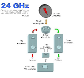
Block diagram is showing the "guide line" and the idea how to assemble a simple transverter. The transverter was built around the down/up converters as a separate blocks. The 24 GHz sides of converters are already prepared for the WR-42 waveguide flange connection and the good practice on this bands is to avoid unnecessary waveguide/coax transitions, SMA connectors, semi-rigid cables and all other lousy parts. Instead of lousy coaxial relay for the antenna RX/TX switching I use the 3 port WR-42 waveguide circulator. No need for fancy smart sequencers and 24 volts DC relay supply. The converters are connected directly to the waveguide circulator. The third port is connected through the short peace of flexible waveguide to the antenna.
The YIG oscillator should work on half or even one third of required local oscillator frequency because of the fact that multipliers are already included in the converter units. The signal from the YIG oscillator is supplied to the converters through the 3 dB splitter.
According to the available data, both IF converter ports are covering the range from 400 MHz to 4 GHz, so wide range of IF frequencies are available. I choose 438 MHz and 1298 MHz for the IF due to easy tuning to the "round" frequency. All parts from the picture down below are commercial radio parts and we do not require expensive measuring equipment to tune and check the finished transverter. All job can be done using the "LNB diode" power indicator/meter and a frequency meter or a surplus wave-meter.
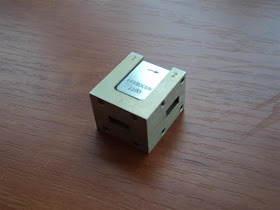
This is the "heart" of the transverter. Both, up and down converters are connected to the circulator (Ports 1 & 2) to obtain the best isolation and the short peace of the wave guide is connected to the Port 3 where antenna should be connected. L.O. and I.F. SMA connectors are protected with the plastic caps. Separate I.F. and L.O. ports are available, so there is a possibility to use different up/down bands for the base radios.
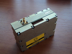
Down-converter is really small but with excellent characteristics. The noise figure is around 3dB and the conversion gain is 22dB. As I already mention the IF is covering the wide range from 400 MHz up to 4 GHz. Very convenient is that the down-converter is requiring LO/2 or LO/3 for a proper operation and the level of the signal should be around 10 dbm. As the LO multiplier is inside the converter we can use any 7/8 GHz or 11/12 GHz oscillator depending on the IF we want to use. The converter require positive 6.5 volts and the negative -5 volts supply. The RF antenna port is accessed through the standard wave guide connection WR-42 size. The inside L/4 pin is probably bent and look odd. Do not try to touch or correct the position of the pin because the pin is matched for the best RL already. The IF and the LO ports are using standard SMA connectors.
The up-converter is using the same approach to reach the 24 GHz band. The local oscillator should work on LO/2 or LO/3 frequency giving out 8 db of the signal. This will be enough power for internal multiplier to produce the signal for the mixer where 0 dbm of IF signal is required. The IF is again covering the range from 400 MHz up to 4 GHz. The up-converter sample that I have from the TRW miliwave company has the gain of 28 db with the IP3 of 30 dbm. The output power is from 23.7 - 26.5 dBm. Consumption is 617mA / 12 V dc power supply. The output RF port has the standard WR-42 waveguide flange connection ready for WR-42 circulator. Again, do not try to touch or modify L/4 waveguide inner pin even it is bended. It looks strange, but this is done by the factory matching the unit to give us the best results. The I.F. and L.O. ports are using the standard SMA female connectors. Recently, I saw a couple of similar units on the e-bay that are advertised together with the isolator ready for WR-42, with some lower output power than mine sample, but with the very good price. The seller advertise that the unit can be used as the beacon, if no IF signal is supplied the module is working as a simple multiplier. Depending of the applied L.O. frequency, a simple 24 GHz beacon can be built. Very useful is also the DET pin (detector) to monitor the output power simply by connecting the voltmeter.
What I can see from some already built transverters and written articles, one on the problem was the antenna switching. Some coaxial relays are rated up to 24 GHz but the loss are high. Some authors are using manual waveguide switches while the others are using mechanical parts with the electrical motors for the same purpose. There are also low loss waveguide switches, mostly home-brew like the one from the I3OPW but they are bit expensive. If we plan to use a low output power a simple solution can be 3 port circulator. The one I am using have the isolation of at least 25 dB and loss of 0.3 dB. This can be enough to protect the RX downconverter from burning the front-end. As the circulator is WR-42 flange ready it is easy to connect the converters straight without any adapter. Using the circulator will save us from using the sequencer and 24V DC required for commercial grade coaxial relays.
The up and down converters are requiring the the same level of the signal from the local oscillator. The easiest way to do that is by using a simple 2 port power divider. As the L.O. is working from 11-12 GHz and the appropriate divider can be purchased from the e-bay or can be found on the flea market. 3 dB loss will require the 11 dBm of the L.O. output power to reach at least 8 dB of the signal on each output port.
As already mentioned, the converters are requiring the LO/2 or LO/3 to work properly. There are several ways of doing it, and after comparing some market prices, I choose to use the YIG PLL oscillator working on the LO/2 frequency. This may look quite expensive, but it is NOT!! It is very strait and simple and no tuning is required comparing to the endless multiplier chains used in some oscillators. Making the L.O. in old fashioned way will require the good quality X-tal (30 USD), some filters (more USD), MMICS (even more USD) and some good quality laminate. Of course, the housing, heater for the oscillator and some instruments and time to tune properly all the multiplier chains. Of course, at the end the frequency stability will always be questionable comparing to the commercially available products. Looking through the e-bay where many different types fo YIG are available, I purchase the Verticom MTS1500e-151-01 YIG PLL oscillator (from the picture) covering the range from 11.2-12 GHz. E-bay price 75 USD.
This type of YIG PLL oscillator require the SPI control. The job has been already done by the group ( Dave Robinson, WW2R, G4FRE ) in their project where simple PIC micro controller was developed for the SPI control. All you need is PIC 12F675 loaded with the proper code, a few voltage regulators and you are ready to have frequency stable 10dBm signal out from the YIG oscillator. MTS1500e-151-01 is not covering wide frequency range but enough to use IF of 432 MHz or 1296 MHz. The advantage is the lower phase noise comparing to the wide frequency coverage YIG oscillators. This YIG has the internal oscillator and the reference signal of 26.25 MHz with the step of 0.416667 MHz. To make the calculation easy we have already prepared excel sheet with all formulas where code-words were created entering only the YIG model and the required frequency. Nice feature is that the microcontroller is capable of creating two different frequencies so I use this feature to generate the L.O. signals for 432 MHz or 1296 MHz IF radio. As the PLL step is odd number not every "round" IF frequency is available but my radio is covering both, 438 MHz for the L.O. output 11805 MHz and the 1298 MHz for the L.O output 11375 MHz. Quickly, using just a simple switch any frequency can be selected for the operation.
The controller was assembled on the small pcb together with the 5v regulator for the 12F675, while the power required for the YIG oscillator is obtained through the voltage regulators 7808 and 7812 mounted on the small heatsink. At the end, complete unit is requiring only 13-15V power supply. The small LED on the PCB is going on only when there is no PLL lock, just briefly at the power-up. Simple way of checking the YIG is using the old wave meter and a simple power meter/indicator. A minute after powering the YIG , stable frequency dip on the wave meter can be found indicating the L.O. output frequency. Switching of and resetting the power back, the time required to reach the same frequency can be measured giving us the idea how much the YIG oscillator need to stabilise on the correct frequency. In my case, after 30 seconds the YIG was ready for narrow band operation. This time is required for heating the reference oscillator inside the YIG oscillator. Connect the SMA output using the low loss semi-rigid coaxial cable with the power divider and further to the converters and the first test can be done even without antenna. Actually, the open waveguide will give us some 6dB of the gain.
Of course, some kind of antenna should be used instead of just a waveguide. Building the microwave antenna that will work on this band is not an easy task. It may look simple and straithforward from one point of view but huge precision is required to meet the low SWR. Simple horn antenna can be a good start, or penny feed with the parabolic reflector is also good choice for the homebrewer's but at the end you will require some kind of measurement to prove that you antenna is actually working.
I prefer to use commercially fabricated antenna for the 24GHz band where no tuning is required. This option can cost you a lot of money for a small antenna if you are buying new one. Good idea is to check the flea market where old cell link equipment can be found. The best and cheaper source is to "Know a guy who knows a guy" :-) Not so many people use this bands today and sometimes this "pots" are available for the beer or two. Just connect the wave guide to the original flange and you are ready to conquer the last microwave centimeter band.
Do not even think to "tune" the feed for the best signal. If antenna is not damaged, it will work more than good on our ham frequencies.


Thanks very much for this informative introduction to 24GHz. I look forward to seeing and reading more about your experiments in this area!
ReplyDelete73 Ben VK2BEN
Appreciated
ReplyDeleteFlexible waveguide
Hello, Do you need an emergency loan to address your financial needs? We offer loans ranging from 3,000.00 to 100,000,000.00 EUR, we are reliable, powerful, fast and dynamic, without credit control and we offer a 100% guarantee for foreign loans during the transfer period. We have also issued a loan in all currencies with a 2% interest rate for all loans .... If you are interested, contact us through Via (Whats App) number:+919394133968 patialalegitimate515@gmail.com Mr Jeffery
ReplyDelete
ReplyDeleteGET OUT OF FINANCIAL MESS WITH THE HELP OF drbenjaminfinance@gmail.com
I have been in financial mess for the past months, I’m a single mum with kids to look after. My name is REBECCA MICHAELSON, and am from Ridley Park, Pennsylvania. A couple of weeks ago My friend visited me and along our discussion she told me about DR BENJAMIN OWEN FINANCE of (drbenjaminfinance@gmail.com); that he can help me out of my financial situation, I never believed cause I have spend so much money on different loan lenders who did nothing other than running away with my money. She advised, I gave it a try because she and some of her colleagues were rescued too by this Godsent lender with loans to revive their dying businesses and paying off bills. so I mailed him and explain all about my financial situation and therefore took me through the loan process which was very brief and easy.. After that my loan application worth $278,000.00USD was granted, all i did was to follow the processing and be cooperative and today I am a proud business owner sharing the testimony of God-sent Lender. You can as well reach him through the Company WhatsApp +19292227023 Email drbenjaminfinance@gmail.com